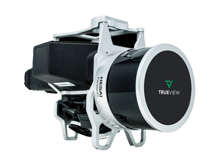
GeoCue’s TrueView 515 is simply the best performing LIDAR/Camera system in the mid price range. This compact 3D Imaging System has impeccable definition along wires, superior ground cover beneath vegetation and sensitivity like we’ve never seen in this class system.
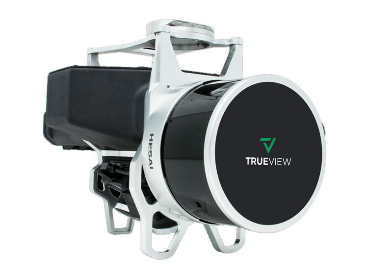
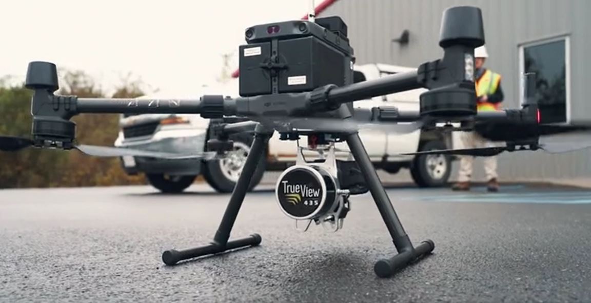
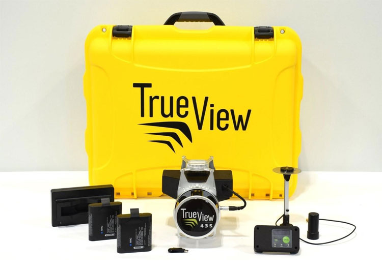
TrueView 435 is the most economical platform for utility-grade mapping. GeoCue’s TrueView 435 is our next generation compact 3D Imaging System that has sensitivity needed for infrastructure mapping. In addition, its superior ground capturing capabilities for lightly vegetated areas make this the most economical platform for utility grade-mapping.
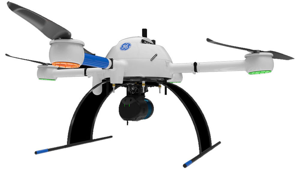
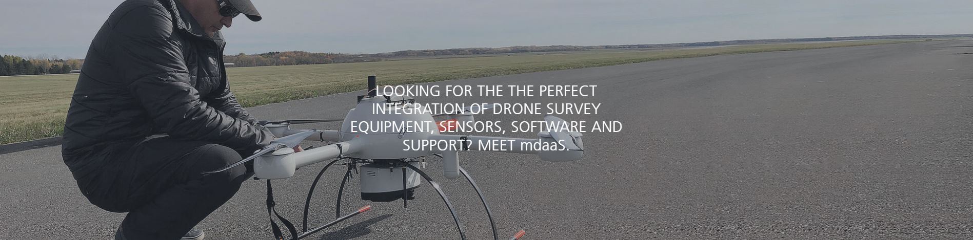
mdLiDAR1000UHR: THE BEST LIDAR POINT DENSITY AND DATA QUALITY EVER OFFERED ON THE MD4-1000 PLATFORM
mdLiDAR1000UHR means ultra-high resolution via a 32-channel LiDAR sensor, fully integrated with an improved 72.5° field of view camera. This translates to more point density, better detail, and improved deliverables. The survey equipment, LP360 Drone software, workflow, training, and support work together to make you more productive than ever.
Who Should Consider This System:
Professionals responsible for geospatial data collection should consider mdLiDAR1000UHR to support the following tasks.
Digital twin creation and maintenance
Corridor mapping
Mining (volume calculation)
Construction site monitoring
Environmental changes (time series)
Forestry
Contour mapping
Planning, leveling, excavation
Archaeology and cultural heritage
Highway construction
Precision agriculture
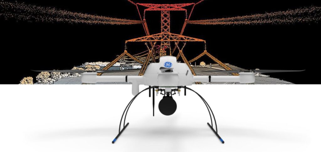
LiDAR SURVEY EQUIPMENT + LP360 DRONE = EXTREME GEOSPATIAL PRODUCTIVITY, NOW IN ULTRA HIGH RESOLUTION
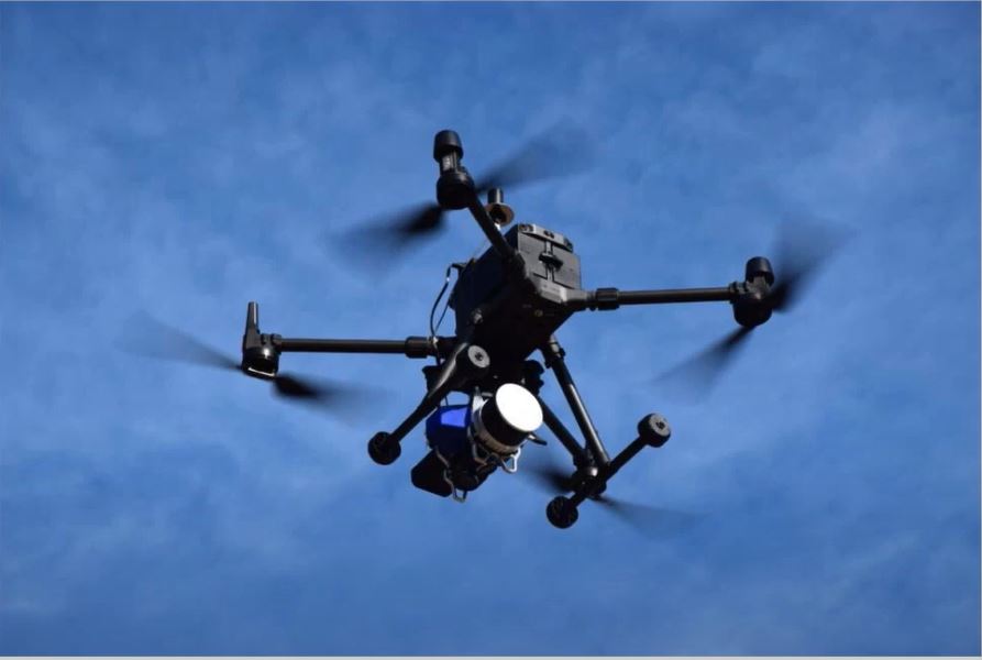
Microdrones has developed an end-to-end LiDAR solution combining a drone, a LiDAR payload, a fully integrated LiDAR processing and photogrammetry software workflow, and world class support to consistently provide quality deliverables.
mdLiDAR1000UHR and UHR Lite is a fully integrated system for producing 3D pointclouds optimized for land surveying, construction, oil & gas and mining applications.
Improved image acquisition precisely configured to match the laser scanner field of view enables compatibility with streamlined data processing modules within LP360.
Each LiDAR channel of the mdLiDAR1000UHR and UHR Lite is boresight calibrated to improve the data consistency, therefore providing a reduced Standard Measurement Uncertainty.
Improved image acquisition precisely configured to match the laser scanner field of view enables compatibility with streamlined pointcloud colorization and FORMap data processing modules within the mdInfinity platform.
md4-1000
Robust, powerful, stable and dependable. Build your business on this versatile platform, now with 10% increased motor efficiency as part of the Industrial drone line.
Charger & Flight Battery
One md4-1000 flight battery and charger for maximum flight endurance.
Rugged Carrying Case
Bring your Microdrones UAV to tackle missions in the toughest corners of the Earth.
LED Light Rings
Efficient LED light rings provide enhanced visibility in the sky, with configurable color schemes for compliance with your country’s requirements.
Integrated Cooling Covers
Patent Pending motor covers enhance cooling and motor longevity.
Mag-less Navigation
Drone navigation is more robust and less subject to magnetic field interference with no need for magnetometer during flight.
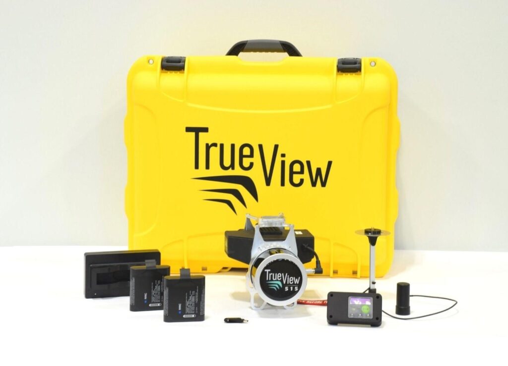
What’s in the box:
PLATFORM
md4-1000 Robust, powerful, stable and dependable. Build your business on this versatile platform, now with 10% increased motor efficiency as part of the GE Industrial line.
Charger & Flight Battery One md4-1000 flight battery and charger for maximum flight endurance.
Rugged Carrying Case Bring your Microdrones UAV to tackle missions in the toughest corners of the Earth.
LED Light Rings Efficient LED light rings provide enhanced visibility in the sky, with configurable color schemes for compliance with your country’s requirements.
Integrated Cooling Covers Patent Pending motor covers enhance cooling and motor longevity.
Mag-less Navigation Drone navigation is more robust and less subject to magnetic field interference with no need for magnetometer during flight.
COMMUNICATIONS
Encrypted Digital Data Link. Conveniently command and control your survey equipment using your tablet. Encryption provides additional security for project and plan data.
mdRC Proven, professional controls and telemetry keep you in control when you need it most, using a second radio link.
Extended Communication Range OperationSubject to local regulations, select markets within the United States.
Multiple Tablet Control(Optional, available upon request) Control the drone from multiple tablets. Take off from Point A with Tablet 1, control at Point B with Tablet 2, etc. Helpful for corridor and BVLOS applications
Remote ID EnabledBroadcast device enabled to comply with unmanned traffic management systems and remote ID requirements.
PAYLOAD
Fully Integrated High Resolution LiDAR & Camera A lightweight, downward oriented LiDAR solution that efficiently scans up to a 120° field of view.
Applanix APX-15 UAV DG Compact single-board module with survey-grade GNSS receiver and a precisely calibrated IMU for mapping.
SURVEY EQUIPMENT SOFTWARE
mdCockpit Tablet Software Simple swipes of the finger help you plan your survey area, monitor progress, and control your flight on your Android tablet.
Tap & Fly Easy remote-free tablet flight execution.
DATA PROCESSING SOFTWARE INCLUDED
LP360 Drone is a powerful ecosystem that will enable you to quickly and efficiently process geospatial data.
Your system will include LP360 Drone, as well as Strip Align and Desktop Photo Add-Ons.
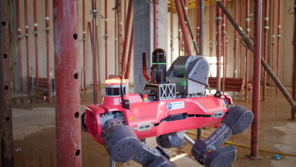
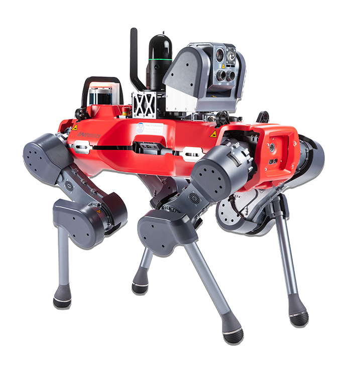
ANYmal is the ultimate UGV (Uncrewed Ground Vehicle) and KukerRanken is the first dealer in the USA with this amazing product.
AEC, Public Safety, Surveyors, and Inspection professionals all benefit from AI-powered ANYmal.
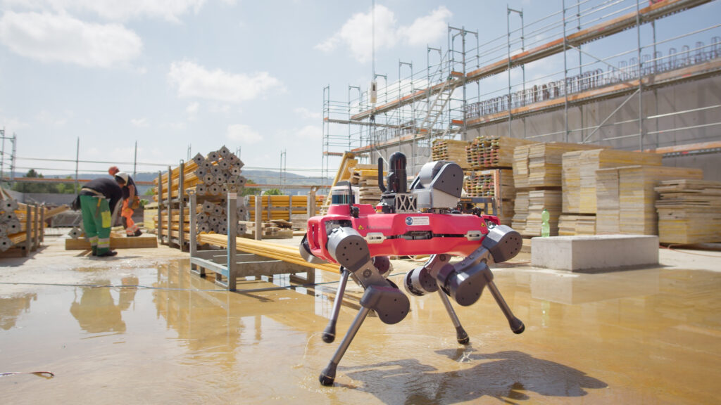
This technology does not require an operator (all other UGV require an operator at this time), and with it’s IP67 rating, can manage any environment regardless of how wet or rugged the operations area may be.
KukerRanken offers the ANYMal with the Leica BLK ARC sensor system, or without.
The ARC adds high end mobile scanning to the system, with mobile mapping. Alternatively, other HDS scanners may also be mounted for static scanning.
ANYmal is unique in being a machine learning-based system vs competitors being model-based systems. ANYmal is capable of on-the-fly decisions, enabling the ANYmal to operate in environments where other systems may fail.
Additionally, the ANYmal is a complete “commercial off the shelf” solution. Competitors are platform systems, meaning the user buys the UGV, and then works with third-parties to create the useable solution. ANYmal, as offered by KukerRanken, is capable of scanning, searching, inspecting, measuring, or modeling data within minutes after purchase.
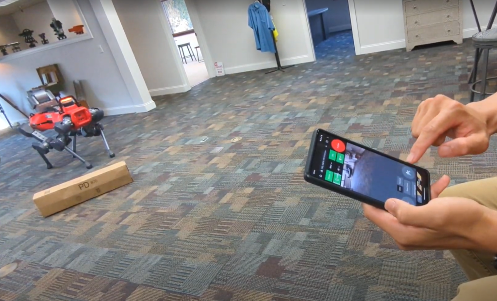
The ANYmal may be operated by an operator, or set up for automated inspections with no operator input. ANYmal may also be controlled from remote environments anywhere in the world, enabling ANYmal to be a true robotic responder, inspector, or BIM tool without human input.
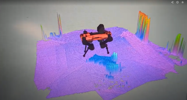
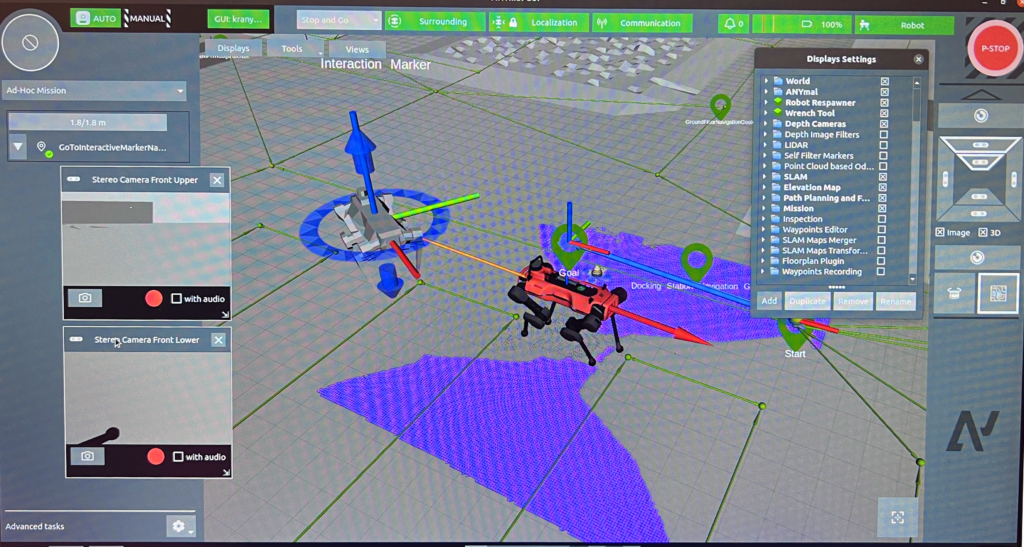
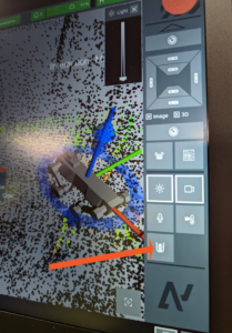
ANYmal creates and understands the environment through both LiDAR and Depth Cameras. In the image to the left, Depth Cameras are used to “map” and be aware of obstacles/potential obstacles in the environment. ANYmal even has modes where it can “test” the height of an object to determine if it should step over, or go around the obstacle.
The Depth Cameras may be used to identify April tags on the ground, whether for inspection points or for the docking station. April tags are used by the ANYmal to identify its docking (charging) station, and auto-dock for automated charging.
Seen on the left, LiDAR is also used to “map” and understand the environment. This enables the ANYmal to confidently operate in virtually any environment without concern for obstacle interference or challenges in terrain, rough rocky hills, rubble piles, or other difficult environments where other UGV are unable to operate.
ANYmal’s integration with other sensors provides the greatest flexibility available in any scenario. Integration allows users to control third-party sensors with the ANYmal remote, software application, or in fully-automated, operator-less modes.
Imagine for example, being able to plan, execute, and deliver a UGV mission without leaving the office, with the UGV being on another continent! Currently, only ANYmal is capable of this sort of operation.
HBC Remote, computer driven, tablet, mobile phone, or automated operation, the ANYmal is vastly superior to any other solution in build quality, intelligence, payload selection, endurance, ability to operate in rugged or harsh environments, and user-friendly operation.
With standard thermal camera, RGB camera, zoom camera, LiDAR, and other sensors built into the ANYmal, users always know where the UGV is operating, what it’s sensing, observing, and moving towards. Integration for additional payloads is available for virtually any type of environmental requirement, including optional gas detectors, and other tools. In a Machine before Human scenario, ANYmal is the only choice where reliability, confidence, and success are mission requirements.
Waypoints are created inside environments. Each waypoint enables UGV positioning, attitude (where it’s facing), and actions. Actions may control where the cameras point, zoom, capture data, engage third-party sensor systems, and more.
A SLAM map of the environment may be used to navigate the UGV through a visual representation of the area/navigable space, or monitored without the SLAM enabled allowing for a clean view of where the UGV is operating.
The ANYmal is capable of manually capturing images while being manually operated (either local or remote), or being instructed to automatically capturing images in a specific location. Video with audio, photographs, thermal images from the included FLIR camera, user-determined zoom, and output from third-party sensors (such as the BLK ARC) may be activated, executed, and downloaded for realtime or post-mission analysis.
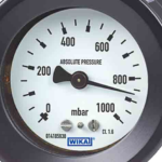
ANYmal is capable of reading virtually any kind of indicator, with user-defined parameters for successful operation or component failure. For example, a user may set an ideal/safe pressure range. When ANYmal senses an anomoly, the anomoly may be reported in real-time to an operator or control station, or the data may be merely collected and responded to post-inspection.
ANYmal is capable of reporting with static images or video (with or without audio), sent to the control station or operator.
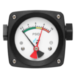
Digital gauges/indicators are sensed/managed in the same way as analog gauges; ideal/appropriate parameters may be set by the operator/controller, and anomolies/out of parameter readings may be real-time reported or delayed until the inspection is complete.
ANYmal also read differential/range gauges, and report when the range is out of standard/user-defined parameters, and report back to the operator or control station. Warnings may be viewed by anyone with a web connection on virtually any platform whether Windows, Android, Mac, or iOS.
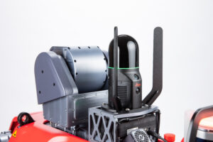
Many use cases benefit from mobile scanning from systems such as the Leica BLK ARC system, feeding scan data in real-time to the operator, enabling scans in-motion.
Alternatively, the ANYmal may be configured for static scanning.
The Leica BLK ARC (Autonomous Reality Capture) payload is an option available from KukerRanken, enabling mobile scanning which may be used as a sole data source, or registered with data from other BLK products such as the BLK2Go, BLK2Fly, and so forth.
Combined with Leica Geosystems Cyclone 3DR, the ANYmal with BLK ARC is the ultimate application for any medium or large site inspection, scan, or BIM capture.
Full integration means the owner or operator does not need to research, and eliminates the confusion of what products may or may not be ready for integration with the ANYmal and its systems.
The ANYmal is the world’s only fully integrated, off-the-shelf ready to scan minutes after delivery (and training).
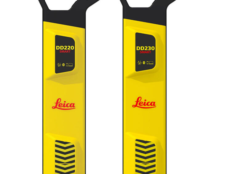
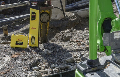
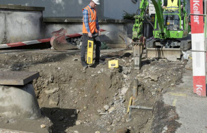
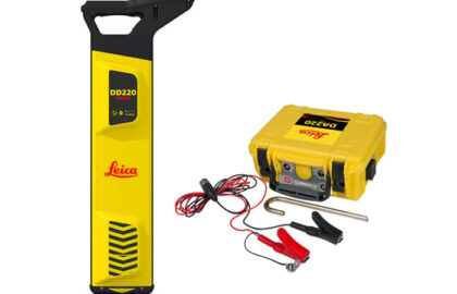
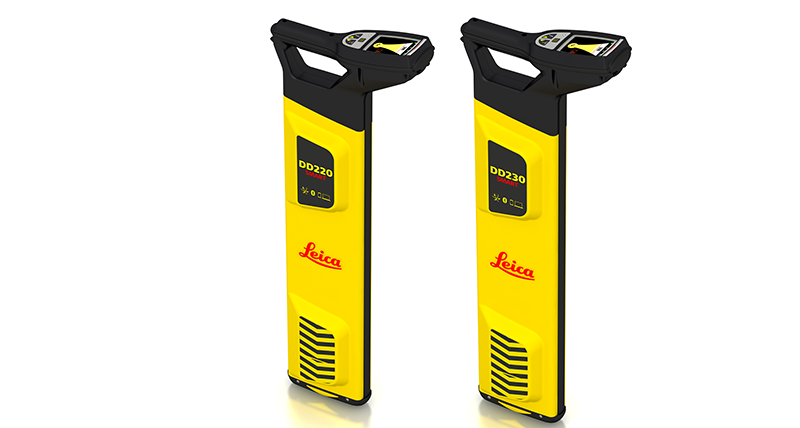
Leica DD SMART Locators & DX Shield Software – Work safer, work faster, work simpler
The new Leica DD SMART utility locator solution, including the DD230/220 cable locator series, DX Shield software and signal transmitters is the only complete portfolio of detection solutions for utility professionals and anyone who is breaking ground. The Leica DD SMART utility locator series uses industry-leading digital signal processing to identify underground assets deeper, faster and more accurately than any other system. Using smart technology, the Leica DD SMART series can record all site usage activities enabling managed safety regimes to flourish. Mapping buried utilities, protecting your assets, personnel and buried utilities has never been more simple with the onboard software. Transfer user logs and data via a hosted service for multiple users, across multiple sites promote smart activities and smart safety.
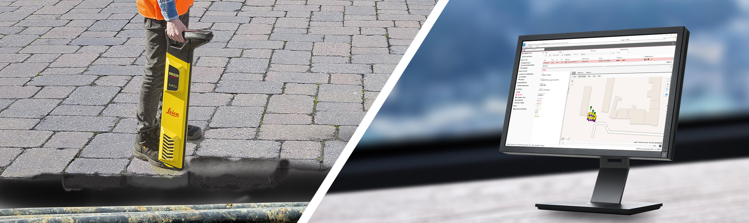
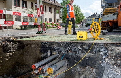
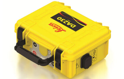
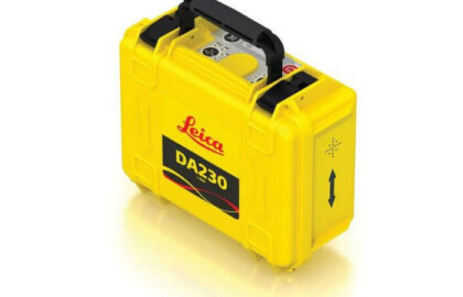
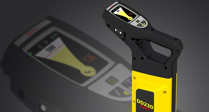
Leica DD SMART Locators & DX Shield Software – Connectivity brings more productivity and saves time.
The Leica DD SMART utility locators and DX Shield software open the door to a connected world, anywhere, anytime. The Leica DD SMART utility locators automatically identify underground assets deeper, faster and more accurately. Understand site activity and utility locator use in greater detail with DX Shield software. The DD230/220 SMART locators are scalable and designed with the latest Bluetooth technology, providing a wire-free connection to field controllers and mobile devices. Connect and download data stored in the DD SMART utility locators’ internal memory, including GPS positioning, and transfer back to the office. USB connectivity provides a convenient connection to DX Office Shield software for data download, analysis and product maintenance. Leica DD SMART utility locators and DX Shield software provide a true single-source solution for all your field activities.
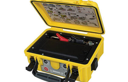
Leica DX Shield – To be more productive and efficient, you need to streamline operations.
The new Leica DX Shield software provides organisations with a single-source solution protecting operators and utilities from harm. Auto sync and access your collected data using your mobile phone. The DX Field Shield app provide operators with a remote transfer tool, linking data from the site to DX Office Shield or DX Manager Shield hosted service. DX Manager Shield provides organisations with a centralised hosted platform for multiple users, across multiple sites. DX Office Shield provides organisations with a scalable local solution on a single-source platform. The success of your business rests on two valuable investments; Leica DD SMART utility locators and Leica DX Shield Software.
Accuracy
Locate and trace accurately your utilities with simple workflows, increasing capability to analyse your assets performance in less time. Personalise and enhance reports to provide actionable outcomes improving site safety and workflows. With the DD SMART utility locators and the DX Shield software more utilities are located. With the locators’ new technology there is a reduced need for multiple sweeps.
Safety
On-board video support, usage alerts and diagnostics to protect your assets and your site workers with a SMART solution. DX Shield software and DD SMART utility locators provide organisations with a mechanism to review and report on assets use, which allows organisations to improve process and products usage.
DX Shield software focuses on site site safety and usage integrity, allowing organisations to gain a better understanding of task performance and site complexities. Easy-to-use reports provide a fast and convenient overview of product use, enabling businesses to identify training needs and skills gaps – leading to reduced utility strikes.
Protect your personnel
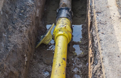
Protect your assets
Protect the infrastructure
Protect your reputation
Give you insights into how your equipment is used
DX Field Shield
Fast and easy transfer of locator data and site documentation.
Connects field activities to DX Manager Shield
Connects field activities to DX Office Shield
Available for Smart phones and tablets
DX Office Shield
Provides product configuration, maintenance and usage analysis.
Connects to CalMaster and link to the web for web calibration verification
Update product firmware and settings
Processes & reports on the locator usage information
Windows PC system
DX Manager Shield
Visualise and report on locator use and site documentation in near real time.
Centralised, accessible information
Processes & reports on the locator usage information
Holds all site documentation e.g. health & safety forms
Keeps all site photos logged in the project folder
Standard, Pro or Expert levels, there’s a version that’s right for your business
Whether flying for the jobsite or flying for fun and family enjoyment, safety is always paramount with UAS (drones). There are the Federal Aviation Administration (FAA) regulations, also known as the FARs, and then there are the “Common-Sense” operational actions that all pilots, regardless of why the drone is flying, should be enacting prior to every flight.
Pre-flight checks aren’t just good practice; they are required by federal law under Part 107, section 49. These rules apply regardless of the reason for the flight (recreational or commercial).
Controllability checks address two of the five preflight requirements for drone flight. Prior to flight, pilots should be checking;
Weather Conditions (Winds, rain, heat, forecasts)
Environmental conditions (people, pets, buildings, trees, other potential threats/chellenges)
Physical state of the drone (props, batteries, fuselage, attached devices)
Any local laws or requirements (not all municipalities allow for drone takeoff/landing on public property)
FAA Airspace authorizations (Waivers, LAANC, etc)
This article focuses on controllability checks, which require less time to perform than the time you’ve already spent reading thus far! They are fast, efficient, and just plain best-practices for any drone mission or plan.
WHAT IS A CONTROLLABILITY CHECK?
A Controllability check (logged as a C/C) provides pilots of an immediate awareness of the aircraft’s readiness for flight, and a means of ensuring all surfaces (props/hull/camera/telemetry/communications) are functioning to expectation and safety requirements.
HOW TO PERFORM A CONTROLLABILITY CHECK
After physically inspecting the props for cracks, ensuring any payload is securely attached to the hull, checking landing gear, motor arms, battery security/locked into body of UAS, and clearing the launch/land area, the aircraft is now ready for flight.
Launch the drone. We recommend launching to an altitude of approximately 12 feet, or higher than the tallest nearby human. Some pilots prefer to launch to an altitude of 2-3 feet, which suffices for controllability check, but does put the aircraft at a level that may harm humans in the event of an aircraft with flight control issues.
Once the drone is airborne and at a safe altitude, we’ll perform a controllability check.
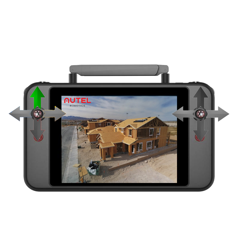
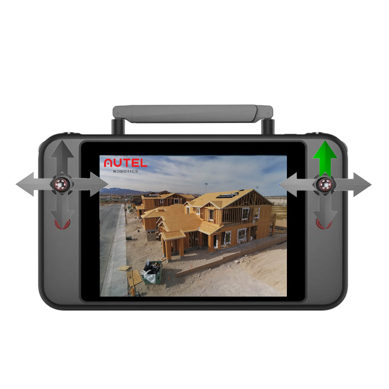
The left stick was already used to launch the drone.
Using the left stick, test the YAW functions on the aircraft. Only the left stick should provide input to the aircraft. Pushing the stick LEFT (9 o’clock position) should cause the aircraft to rotate left. Next, do the same with the left stick pushed to the right. Again, the aircraft should rotate (YAW) to the right.
Next, push the stick down. This should cause the aircraft to descend. Be sure the aircraft remains at a level that is above the heads of anyone in the immediate area. As mentioned previously, we typically perform these maneuvers at approximately 12’/4 meters.
Generally, we begin the controllability check with the left stick, as there is no dimensional movement through use of the left stick; the aircraft hovers in one place and moves within the “column” directly above the launch/land pad. Starting with the left stick is a small nod to the increased risk of horizontal/dimensional movement.
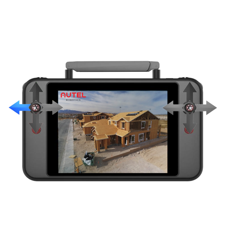
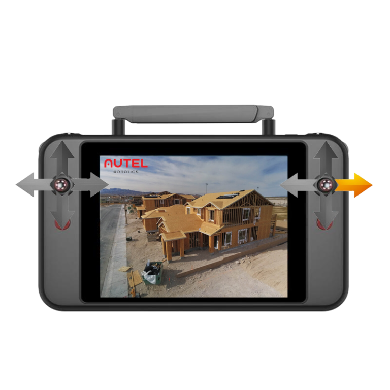
Now that we’re certain the left stick is controlling the aircraft as expected, we’ll move to the right stick.
The right stick is a bit more dynamic, as it controls all horizontal movement of the aircraft, and the aircraft will move forward, backward, roll right, and roll left.
We recommend that the first right stick movement is forward flight, to push the aircraft away from the (assuming pilot is slightly to the right/left and behind the aircraft) pilot, providing a safety buffer in the event of a radio problem.
Now check the other three axis’ of the right stick, checking the roll right, roll left, and backward/reverse flight.
These stick movements do not require “big” moves. In our training, we teach pilots to keep the aircraft in a 24″ square box area. In keeping the flight area very small, the aircraft will not be able to build momentum in the event of any obstacle that might be in the area. Additionally, a small area reduces the load on the battery, ensuring the longest possible flight time.
And that’s all! Once the controllability check is completed and all control surfaces have been verified, the planned missions may begin.
Some pilots (and our policy) is to land the aircraft after the controllability check, and insert a fresh battery prior to beginning any mission. Each organization/business/operation will have their own standards and best practices. If a new, fresh battery was used for the C/C, and the C/C is performed rapidly, there is generally no issue with beginning the mission while the aircraft is hovering after the final stick/control check.
Use your own best judgement; the key is to identifying consistent behaviors, processes, and checks to ensure the aircraft is ready to be flown or put into automated mission modes.
Thanks for reading!
At KukerRanken, we’re dedicated to providing the best UAS information for Architects, Surveyors, Construction companies, and Engineers. When questions arise, we’re here to provide answers.
Purchase a Microdrones MD1000HR between today and May 27, 2022, and save nearly $4000.00 in processing costs.
When a Microdrones MD1000HR is purchased, customers typically purchase one year of limited access data processing. However, for this limited time, KR and Microdrones are offering three free months of unlimited processing, until May 27, 2022. We have units available now, so no need to wait!
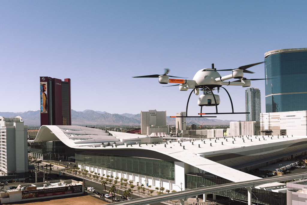
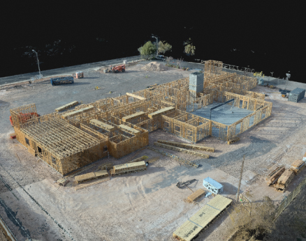
The MD1000HR flies over the Las Vegas Convention Center during upgrades to the parking lot areas, tram areas, and walkways to new West Halls (Spring, 2022)
We do have demo datasets available, and are ready to do an online demonstration of capture, ingest, data processing, deliverable to civil tools, 3DR, Pix4D, and other popular analysis and delivery applications.
KukerRanken also offers industry-focused training for Part 107, practical applications of drones/UAS in Survey, Engineering, or Construction workflows, including Leica software tools and Pix4D products.
Contact Brady, Douglas, Bryan, or Darrell for more information on this short-time opportunity from Microdrones and KukerRanken!
PIX4D for Survey and AEC (Architectural, Engineering, Construction)
AEC/Survey/GIS users of Pix4D benefit from training specifically focused on precision applications of the software. Different than generalized training (which misses many of the nuances and processes required for precision professionals), focused training provides greater confidence and competency when working with Pix4DMapper. Whether it’s a discussion of stakeout, contours, volumetrics, as-built, progress reporting, or, or placing checks in the data capture process to create a solid data capture and analysis background, AEC/Survey/GIS is unique in its use of Pix4D and other analysis and modeling tools.
KukerRanken/SMG training for Pix4D focuses on the needs of the specific vertical use. Engineers, construction teams, architects, surveyors, and other users of the software will find familiar language, datasets, and workflows which are common, comfortable, and consistent with other training events and exercises found in AEC/Survey/GIS workflows.
TWO DAY TRAINING:
Online or in-person
In our two day training course, attendees will learn all aspects of importing, calibrating, processing, and archiving data, as well as best practices for transporting the scene datum to other internal departments and external share of data. Attendees will use data sets (supplied by SMG) relevant to construction practices (as-built, volumetrics, progress reports, BIM), ensuring the scenarios are familiar and relevant.
Attendees will learn to properly file and label data (Pix4D transports best with a specific file structure), import data to Pix4D, properly select coordinate datums, and set up the project. Verification of data capture, how to retrieve flight verification, and ensure an entire area was properly captured, and prep for
processing are all part of the first day of training.
Once the project has been set
up for processing, attendees will learn the most efficient methods of prepping the data
for best-practices deliverables, storing quality reports as part of the case file, and understanding process documentation.
DAY ONE TRAINING:
Setting up folders per jobsite/project
Transferring and backing up data
Learning the interface
Understanding Import of Data
Refining project settings after import
Selecting a coordinate system/datum
Problem solving at import
Verifying data collection/flight path
Storing data, flight path information
Importing GPS data for greater precision
First step processing/Initial Point Cloud
Calibrating uncalibrated cameras
Creating a processing area
Marking control points
Ground controls supported by GPS (total station, rover output, etc)
Manual tie points (in the event no GPS is used)
Reoptimizing and/or rematching images
Second step processing
Densified Point cloud
Texturing
Orthomosiac viewing
DAY TWO TRAINING:
Understanding measurements in the point cloud
Understanding areas in the point cloud
How Models assist viewing, and Orthos for measurement
Cleaning the point cloud/denoising a point cloud
Outputting a Mosiac
Modifying/cleaning the mosiac
Creating deliverables for local and cloud delivery
Ortho
Contour
DSM
Storing/archiving all data relevant to the project
Exporting to other software tools
Exporting surfaces for CAD
Trouble-shooting output/deliverable issues
THREE DAY TRAINING:
Online-only, blended Online/In-person, or In-person
Our most popular offering, the three-day course provides live flight training to officers and CSA personnel.
Live flight training instructs the proper spin-up of the flight, ensuring data is cleanly captured on the first flight, with a focus on both overall scene capture for investigators, as well as data capture for measurables, evidence, and clean deliverables. In this course, attendees will also learn to co-operate remotely piloted aircraft with cell phone photos, crime scene photos, ground-based elements and other data capture. Upon completion of this course, pilots should be confident and competent in the planning and execution of flight for clean, quality-driven data capture, and processing of images for photogrammetry and point cloud delivery in various formats.
DAY ONE TRAINING:
Assessing the jobsite (safety)
Risk mitigation
Determining environmental impacts on data capture (wind, rain, night time, mid-day)
Camera settings for optimal capture/Setting up the camera for manual capture
Best practices for camera use
Night capture
Placement of controls and verification devices
Planning the mission/flight
Secondary capture (terrestrial), hand-held UA capture, and tertiary camera capture
Storing the mission plan/flight data for the case file
Capturing GPS data (where applicable) in scenes for precision and accurate measurement and terrestrial placement
Executing the mission
Video capture of the scene
On-scene verification of data capture
Data backup
Folder structure for Pix4D import
DAY TWO TRAINING:
Setting up folders per case/scenario
Transferring and backing up data
Learning the interface
Understanding Import of Data
Refining project settings after import
Selecting a coordinate system/datum
Problem solving at import
Verifying data collection/flight path
Storing data, flight path information
Importing GPS data for greater precision
First step processing/Initial Point Cloud
Calibrating uncalibrated camera sources
Creating a processing area
Marking control points
Ground controls supported by GPS (total station, rover output, etc)
Manual tie points (in the event no GPS is used)
Reoptimizing and/or rematching images
Second step processing
Densified Point cloud
Texturing
Orthomosiac viewing
DAY THREE TRAINING:
Understanding measurements in the point cloud
Understanding areas in the point cloud
How Models assist viewing, and Orthos for measurement
Cleaning the point cloud/denoising a point cloud
Outputting a Mosiac
Modifying/cleaning the mosiac
Accessing video data for Pix4D processing
Annotating evidence and elements of a scene
Creating deliverables for local and cloud delivery
Ortho
Contour
DSM
Storing/archiving all data relevant to the project
Exporting to other software tools
Trouble-shooting output/deliverable issues
Contact KukerRankenfor information, dates, costs, and training programs.
Pricing is structured for construction/survey businesses and individuals.
All training is bespoke; manuals, work product, and curriculum is variable by organization or individual needs. Prior to scheduling a training course, we prefer to discuss specific needs for specific courses in order to ensure client expectations and needs are clearly met.
Microdrones MD1000HR LiDAR system with DJI Matrice 300/P1 camera
SAVE TIME, GENERATE GREATER REVENUE WITH AERIAL TECHNOLOGY
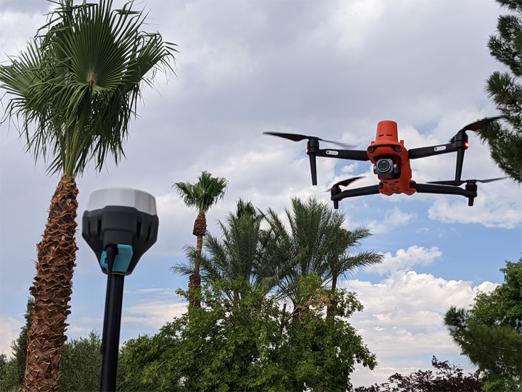
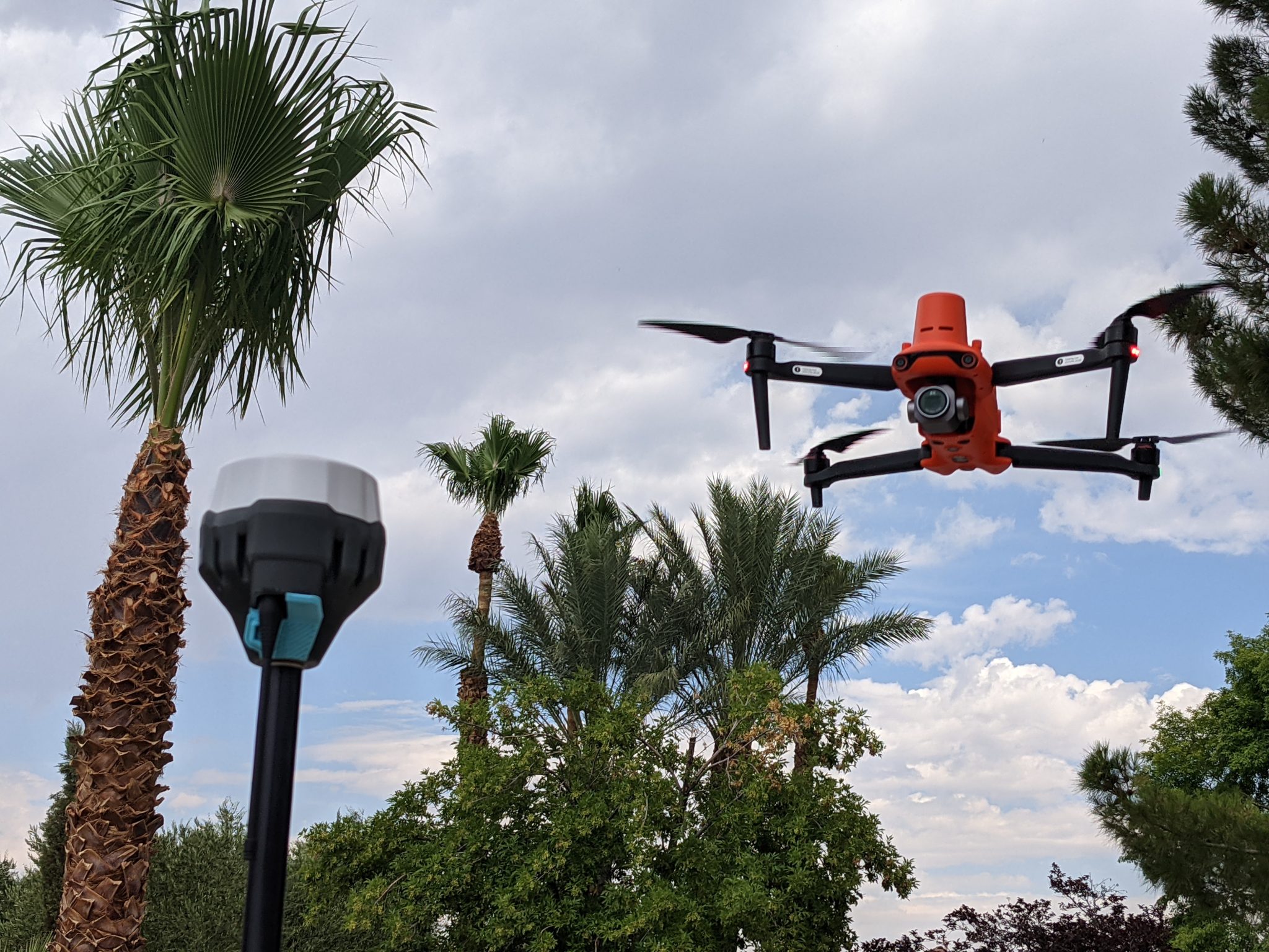
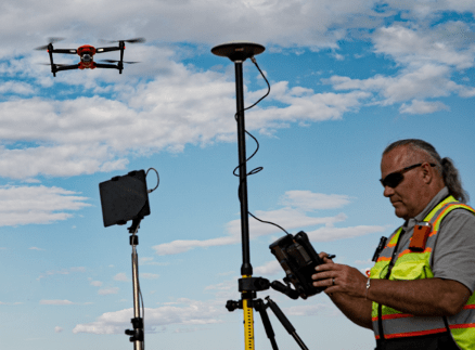
The Autel EVO II Aircraft, coupled with the Emlid RS2 base station are a cost-effective combination for surveyors, construction survey, engineering, etc.
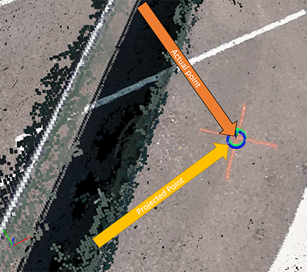
Real-Time Kinematic (RTK) corrections bring significant precision to unmanned aircraft and workflows, even to the point of achieving repeatable precision within 1cm of actual position in a localized dataset.
Adding RTK to an unmanned aircraft enables real-time correctional data to be sent to the aircraft, allowing the aircraft to write corrected information to the metadata captured in the aircraft’s camera/sensor system. This is achieved through the aircraft remote control/ground station controller receiving correctional information from either a network system (NTRIP) or a local base station sending correctional data to the controller. In either case, the corrected positional data is uploaded to the aircraft.
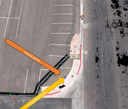
No corrections, no RTK, nearly 10′ from point
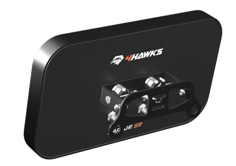
One of the greatest challenges/concerns with an RTK aircraft is to ensure the aircraft is receiving corrections throughout the entire flight. Over large areas where there may be pockets of RF interference from powerlines, trees, buildings, or other obstructions, it’s possible to have a few images without RTK corrections, particularly at the edges of the flight area. One remedy is to add a range extender such as the 4Hawks antenna system to the aircraft’s remote.
The 4Hawks Antenna system assists in ensuring RTK corrections are sent to the aircraft throughout the entire mission area.
RTK systems gain slight benefit from the antenna-only system (autonomous positioning) while adding a base station or NTRIP network correctional system.
No corrections, RTK antenna-only. 13″ from actual
With RTK corrections sent to the aircraft, the point and the aircraft projections are 1 cm from the point.
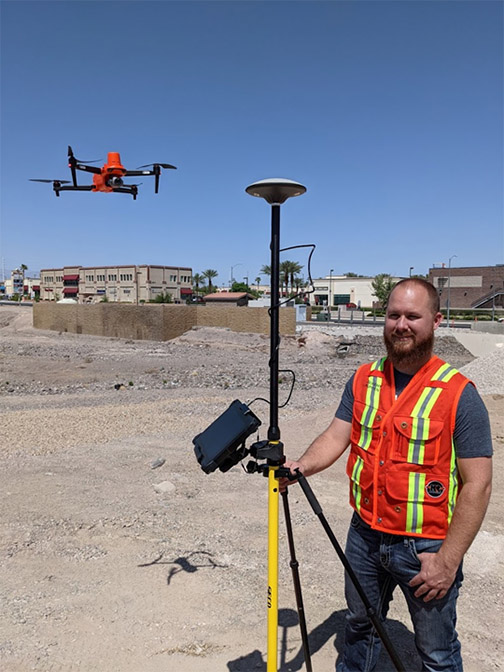
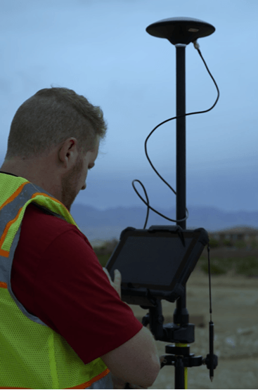
We used a DT Research 301 data collector with a Seco RTK rod and head to verify data from the aircraft’s indicated position, and have since used a Leica GS18i to verify the points.
Jeremy Kippen from the KukerRanken Las Vegas store uses the DTResearch 301 system as a data collector to capture points on the ground, while flying the Autel EVO II RTK aircraft
Incorporating an RTK aircraft into the construction site, survey, engineering project, and many other uses provides a safer, faster, cost-effective means of capturing precise data, no matter the scenario. Topos, DSM, DTM, DEM, orthos, pointclouds, extraction for surfaces, and many other deliverables can become significantly more efficient when proper training and implementation techniques are observed. At KukerRanken, we’re here to help with UAS program development, training from Part 107 to operational techniques, and post-processing best practices.
Contact one of our KukerRanken staff to gain access to datasets demonstrating RTK with drone workflows. We offer Pix4DMapper, Pix4DSurvey, Leica Infinity, Leica 3DR, and many other training programs.
A Deep Insider’s Look at a Rugged Terrain Mission to Investigate a Helicopter Crash with Drones
Crash site investigation with drones has emerged as a leading application for unmanned systems in public safety. Gathering data that can be used by investigators in a courtroom, however, requires careful mission planning. Here, sUAS expert and industry figure Douglas Spotted Eagle of KukerRanken provides a detailed insider’s view of a helicopter crash site investigation.
Unmanned aircraft have become proven assets during investigations, offering not only the ability to reconstruct a scene. When a high ground sampling distance (GSD) is used, the data may be deeply examined, allowing investigators to find evidence that may have not been seen for various reasons during a site walk-through.
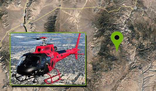
Recently, David Martel, Brady Reisch and I were called upon to assist in multiple investigations where debris was scattered over a large area, and investigators could not safely traverse the areas where high speed impacts may have spread evidence over large rocky, uneven areas. In this particular case, a EuroStar 350 aircraft may have experienced a cable wrap around the tail rotor and boom, potentially pulling the tail boom toward the nose of the aircraft, causing a high speed rotation of the hull prior to impact. Debris was spread over a relatively contained area, with some evidence unfound.
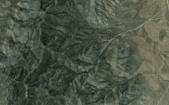
“The helicopter was on its right side in mountainous densely forested desert terrain at an elevation of 6,741 ft mean sea level (MSL). The steel long line cable impacted the main rotor blades and was also entangled in the separated tail rotor. The tail rotor with one blade attached was 21 ft. from the main wreckage. Approximately 30 ft. of long line and one tail rotor blade were not located. The vertical stabilizer was 365 ft. from the main wreckage.”
With a missing tail rotor blade and the missing long line, unmanned aircraft were called in to provide a high resolution map of the rugged area/terrain, in hopes of locating the missing parts that may or may not aid in the crash investigation.
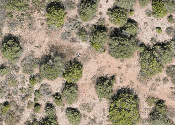
The terrain was difficult and unimproved, requiring four-wheel drive vehicles for access into the crash site. Due to rising terrain, we elected to launch/land the aircraft from the highest point relevant to the crash search area, which encompassed a total of approximately 70 acres.
Adding to the difficulty of finding missing parts was that the helicopter was partially covered in grey vinyl wrap, along with red and black vinyl wrap, having recently been wrapped for a trade show where the helicopter was displayed.
We arrived on scene armed with pre-loaded Google Earth overheads, and an idea of optimal locations to place seven Hoodman GCP discs, which would allow us to capture RTK points for accuracy, and Manual Tie Points once the images were loaded into Pix4D. We pre-planned the flight for an extremely high ground sampling distance (GSD) average of .4cm per pixel. Due to the mountainous terrain, this GSD would vary from the top to the bottom of the site. We planned to capture the impact location at various GSD for best image evaluation, averaging as tight as .2cmppx. Some of these images would be discarded for the final output, and used only for purposes of investigation.
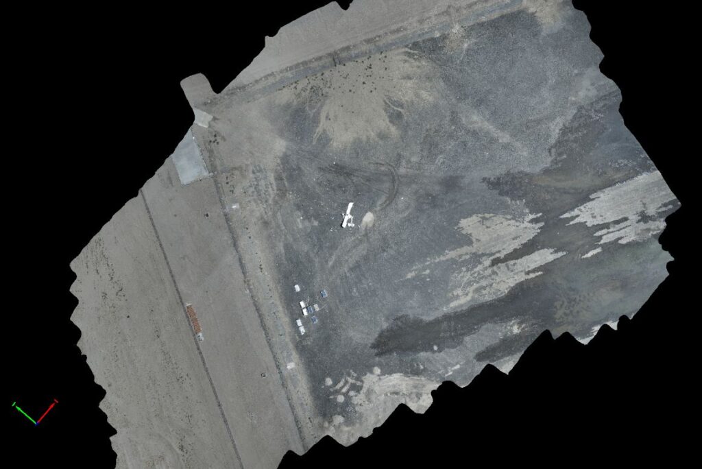
Although the overall GSD was greater than necessary, the goal is to be able to zoom in very deep on heavily covered areas with the ability to determine the difference between rocks and potential evidence, enabling investigators to view the overall scene via a 3.5 GB GeoTiff in Google Earth, and refer back to the Pix4DMapper project once rendered/assembled.
The same scene minus initial marker points.
Although working directly in Pix4D provides the best in-depth view of each individual photo, the Google Earth overlay/geotiff enables a reasonably deep examination.
Using two of the recently released Autel EVO II Pro aircraft, we planned the missions so that one aircraft would manage North/South corridors while the other captured East/West corridors. Planning the mission in this manner allows for half the work time, while capturing the entire scene. This is the same method we used to capture the MGM festival grounds following the One October shooting in Las Vegas, Nevada. The primary difference is in the overall size, with the Pioche mission being nearly 70 acres, while the Las Vegas festival ground shooting area is under 20 acres in total.
Similar to the Las Vegas shooting scene, shadow distortion/scene corruption was a concern; flying two aircraft beginning at 11:00 a.m. and flying until 1:30 aided in avoiding issues with shadow.
Temporal and spatial offsets were employed to ensure that the EVO II Pro aircraft could not possibly collide, we set off at opposite sides of the area, at different points in time, with a few feet of vertical offset added in for an additional cushion of air between the EVO II. We programmed the missions to fly at a lower speed of 11 mph/16fps to ensure that the high GSD/low altitude images would be crisp and clean. It is possible to fly faster and complete the mission sooner, yet with the 3 hour travel time from Las Vegas to the crash site, we wanted to ensure everything was captured at its best possible resolution with no blur, streak, or otherwise challenged imagery. Overall, each aircraft emptied five batteries, with our batteries set to exchange notification at 30%.
Total mission running time was slightly over 2.5 hours per aircraft, with additional manual flight over the scene of impact requiring another 45 minutes of flight time to capture deep detail. We also captured imagery facing the telecommunications tower at the top of the mountain for line of sight reference, and images facing the last known landing area, again for visual reference to potential lines of sight.
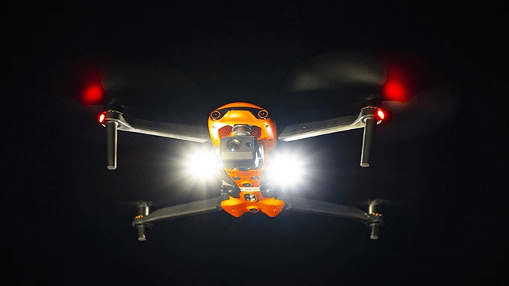
By launching/landing from the highest point in the area to be mapped, we were able to avoid any signal loss across the heavily wooded area. To ensure VLOS was maintained at all times, FoxFury D3060’s were mounted and in strobing mode for both sets of missions (The FoxFury lighting kit is included with the Autel EVO II Pro and EVO II Dual Rugged Bundle kits).
Once an initial flight to check exposure/camera settings was performed, along with standard controllability checks and other pre-flight tasks, we sent the aircraft on their way.
Capturing over 6000 images, we checked image quality periodically to ensure consistency. Once the missions were complete, we drove to the site of impact to capture obliques of the specific area in order to create a more dense model/map of the actual impact site. We also manually flew a ravine running parallel to the point of impact to determine if any additional debris was found (we did find several small pieces of fuselage, tools assumed to be cast off at impact, and other debris.
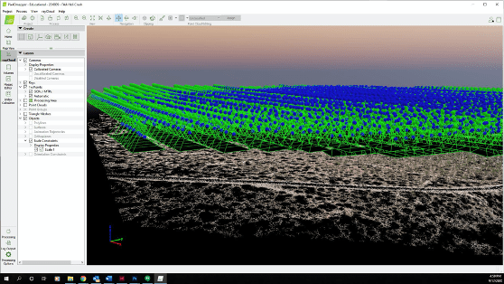
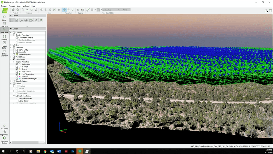
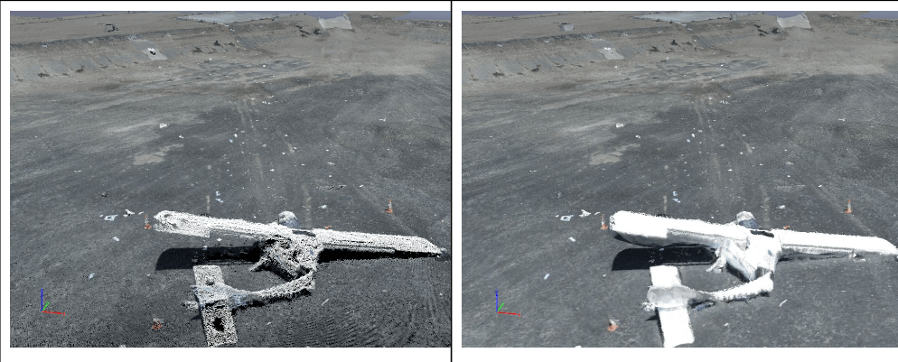
The initial pointcloud took approximately 12 hours to render, generating a high-quality, highly dense initial cloud.
After laying in point controls, marking scale constraints as a check, and re-optimized the project in Pix4D, the second step was rendered to create the dense point cloud. We were stunned at the quality of the dense point cloud, given the large area.
The dense point cloud is ideal for purposes of measuring. Although this sort of site would typically benefit (visually) from texturing/placing the mesh, it was not necessary due to the high number of points and deep detail the combination of Pix4D and Autel EVO II Pro provided. This allowed us to select specific points where we believed points of evidence may be located, bringing up the high resolution images relevant to that area. Investigators were able to deep-dive into the area and locate small parts, none of which were relevant to better understanding the cause of the crash.
“The project generated 38,426,205 2D points and 13,712,897 3D points from a combination of nearly 7,000 images.”
Using this method of reviewing the site allows investigators to see more deeply, with ability to repeatedly examine areas, identify patterns from an overhead view, and safely search for additional evidence that may not be accessible by vehicle or foot. Literally every inch of the site may be gone over.
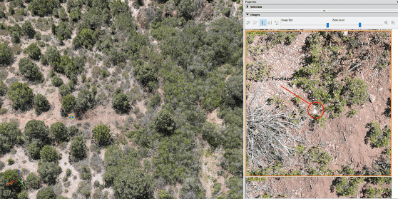
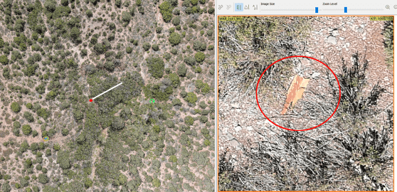
Further, using a variety of computer-aided search tools, investigators may plug in an application to search for specific color parameters. For example, much of the fuselage is red in color, allowing investigators to search for a specific range of red colors. Pieces of fuselage as small as 1” were discovered using this method. Bright white allowed for finding some items, while 0-16 level black allowed for finding other small objects such as stickers, toolbox, and oil cans.
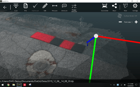
Using a tool such as the DTResearch 301 to capture the RTK geolocation information, we also use the DTResearch ruggedized tablet as a localized pointcloud scan which may be tied into the Pix4Dmapper application. Capturing local scan data from a terrestrial perspective with GCP’s in the image allow for extremely deep detail in small environments. This is particularly valuable for construction sites or interior scans, along with uses for OIS, etc.
Primary Considerations When Capturing a Scene Twin
GSD. This is critical. There is a balance between altitude and propwash, with all necessary safety considerations. Vertical surfaces. In the event of an OIS where walls have been impacted, the ability to fly vertical surfaces and capture them with a consistent GSD will go a long way to creating a proper model. Shadow distortion. If the scene is very large, time will naturally fly by and so will the sun. In some conditions, it’s difficult to know the difference between burn marks and shadows. A bit of experience and experimentation will help manage this challenge.
Exposure. Checking exposure prior to the mission is very important, particularly if an application like Pix4Dreact isn’t available for rapid mapping to check the data on-site. Angle of sun/time of day. Of course, accidents, incidents, crime, and other scenes happen when they happen. However, if the scene allows for capture in the midday hours, grab the opportunity and be grateful. This is specifically the reason that our team developed night-time CSI/Datacapture, now copied by several training organizations across the country over recent years.
Overcapture. Too much overlap is significantly preferable to undercapture. Ortho and modeling software love images.
Obliques. Capture obliques whenever possible. Regardless of intended use, capture the angular views of a scene. When possible, combine with ground-level terrestrial imaging. Sometimes this may be best accomplished by walking the scene perimeter with the UA, capturing as the aircraft is walked. We recommend removing props in these situations to ensure everyone’s safety.
What happens when these points are put aside?
This is a capture of a scene brought to us for “repair,” as the pilot didn’t know what he didn’t know. Although we were able to pull a bit of a scene, the overexposure, too-high altitude/low GSD, and lack of obliques made this scene significantly less valuable than it might have been.
Not understanding the proper role or application of the UA in the capture process, the UA pilot created a scene that is difficult to accurately measure, lacking appropriate detail, and the overexposure creates difficulties laying in the mesh. While this scene is somewhat preserved as a twin, there is much detail missing where the equipment had the necessary specifications and components to capture a terrific twin. Pilot error cannot be fixed. Operating on the “FORD” principle, understanding that FOcus, exposuRe, and Distance (GSD) cannot be rectified/compensated for in post processing means it has to be captured properly the first time. The above scene can’t be properly brought to life due to gross pilot error.
“ALWAYS PUT THE AIRCRAFT OVER THE PRIMARY SCENE LOCATION TO CONFIRM EXPOSURE SETTINGS, KEEPING ISO AS LOW AS POSSIBLE. USE ISO 50-100 IN MOST OUTDOOR SCENARIOS TO OBTAIN THE BEST IMAGE. NEVER USE OVERSATURATED PHOTO SETTINGS OR LOG FORMATS FOR MAPPING.”
Ultimately, the primary responsibility is to go beyond a digital twin of the scene, but instead offer deep value to the investigator(s) which may enhance or accelerate their investigations. Regardless of whether it’s a crash scene, insurance capture, energy audit, or other mapping activity, understanding how to set up the mission, fly, process, and export the mission is paramount.
Capturing these sorts of scenes are not for the average run n’ gun 107 certificate holder. Although newer pilots may feel they are all things to all endeavors benefitting from UA, planning, strategy, and experience all play a role in ensuring qualified and quality captures occur. Pilots wanting to get into mapping should find themselves practicing with photogrammetry tools and flying the most challenging environments they can find in order to be best prepared for environmental, temporal, and spatial challenges that may accompany an accident scene. Discovery breeds experience when it’s cold and batteries expire faster, satellite challenges in an RTK or PPK environment, planning for overheated tablets/devices, managing long flight times on multi-battery missions, or when winds force a crabbing mission vs a head/tailwind mission. Learning to maintain GSD in wild terrain, or conducting operations amidst outside forces that influence the success or failure of a mission only comes through practice over time. Having a solid, tried and true risk mitigation/SMS program is crucial to success.
We were pleased to close out this highly successful mission, and be capable of delivering a 3.5 GB geotiff for overlay on Google Earth, while also being able to export the project for investigators to view at actual ground height, saving time, providing a safety net in rugged terrain, and a digital record/twin of the crash scene that may be used until the accident investigation is closed.


 Second step processing