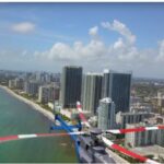


2022 is clearly the year of LiDAR.
At all of the UAS shows in the USA, Mexico, Canada, and EU, the hot topic is LiDAR in 2022, and 2023 is ramping up to be more of the same, with significant growth.
LiDAR is a “LIght Detection And Ranging” sensor, utilizing a laser, position-controlled mirror, an IMU (Inertial Measurement Unit) and internal processing to record geolocation data.
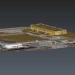
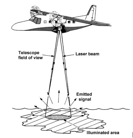
A LiDAR sensor emits a pulse of light towards the target (ground) The light is reflected from the surface/earth (a point) and returned to the sensor. The receiver detects the returning signal and calculates the distance the light has traveled. Using the position of the sensor, mirror, IMU, the direction in which the light was sent and the distance calculated. Following this return and calculations, the 3D position where the signal was returned may be determined. With millions of reflections striking a terrestrial surface and returning to the LiDAR sensor, these contact “points” are used to generate the 3D model or ortho re-creating the target area in a digital environment.
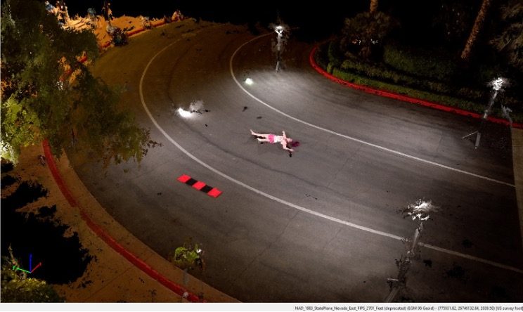
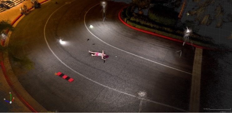
Because LiDAR sensors generate their own signal pulse, illumination from other sources (for example, the sun), many LiDAR operator/pilots capture data at night. As long as there is nothing interfering between sensor and surface it is therefore possible to collect data below cloud cover (or in the dark). LiDAR can offer extremely flexible access to areas requiring scans, given the ability to fly at night, or when cloud cover has a negative impact on a site where photogrammetry may not be possible due to lighting conditions.
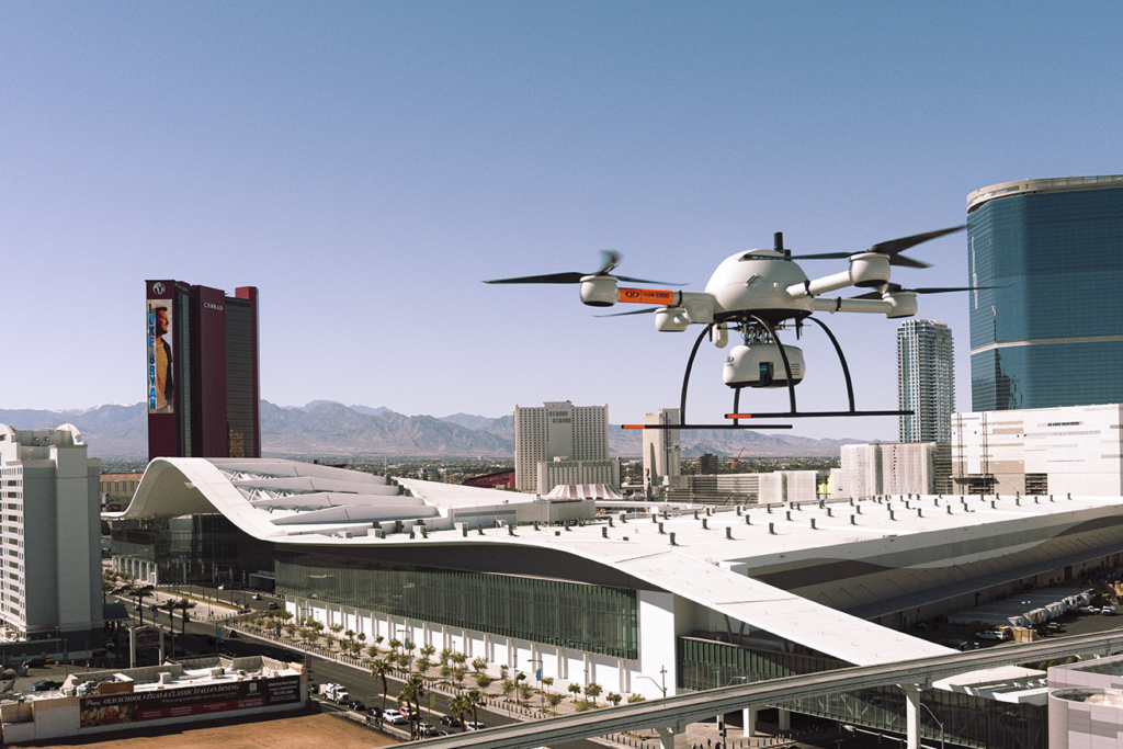
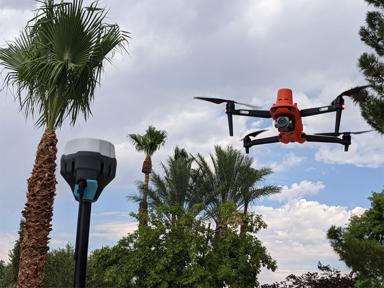
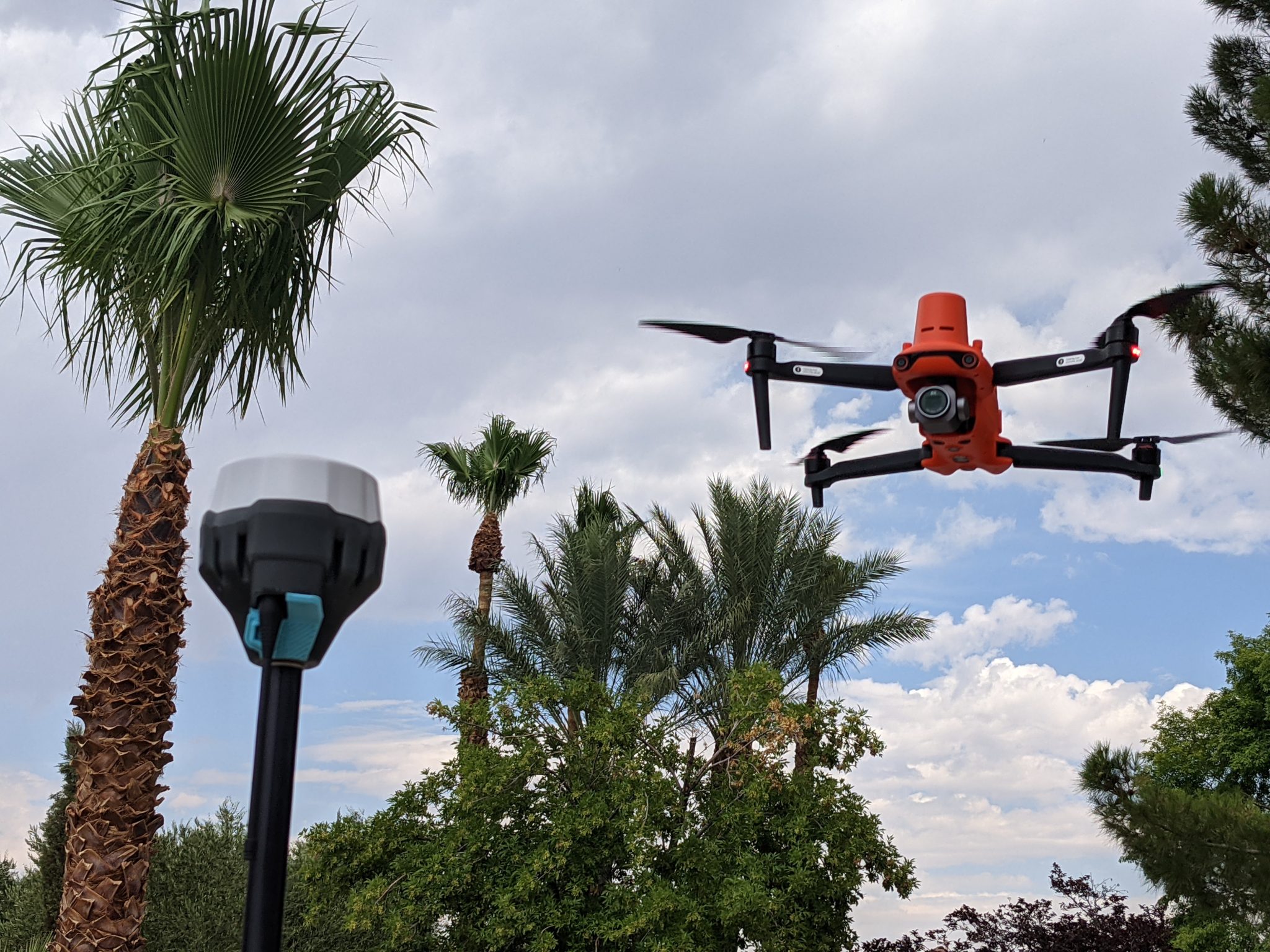
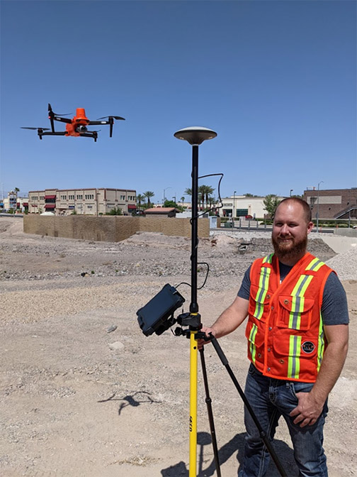
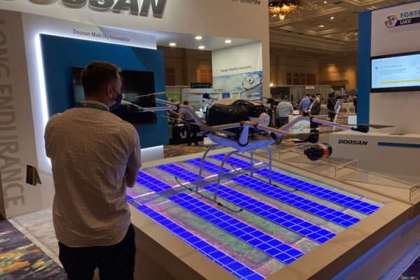
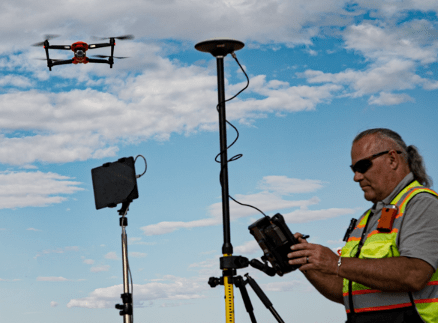
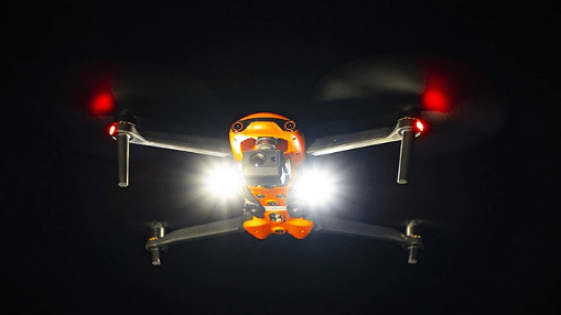
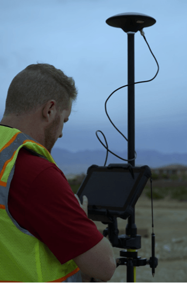
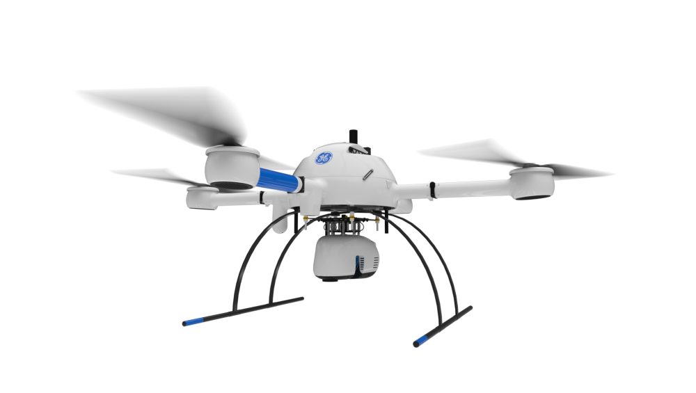
LiDAR sensors were previously relegated to fixed wing or rotary aircraft due to weight and cost, now accessible by any mid or heavy-lift UAS.
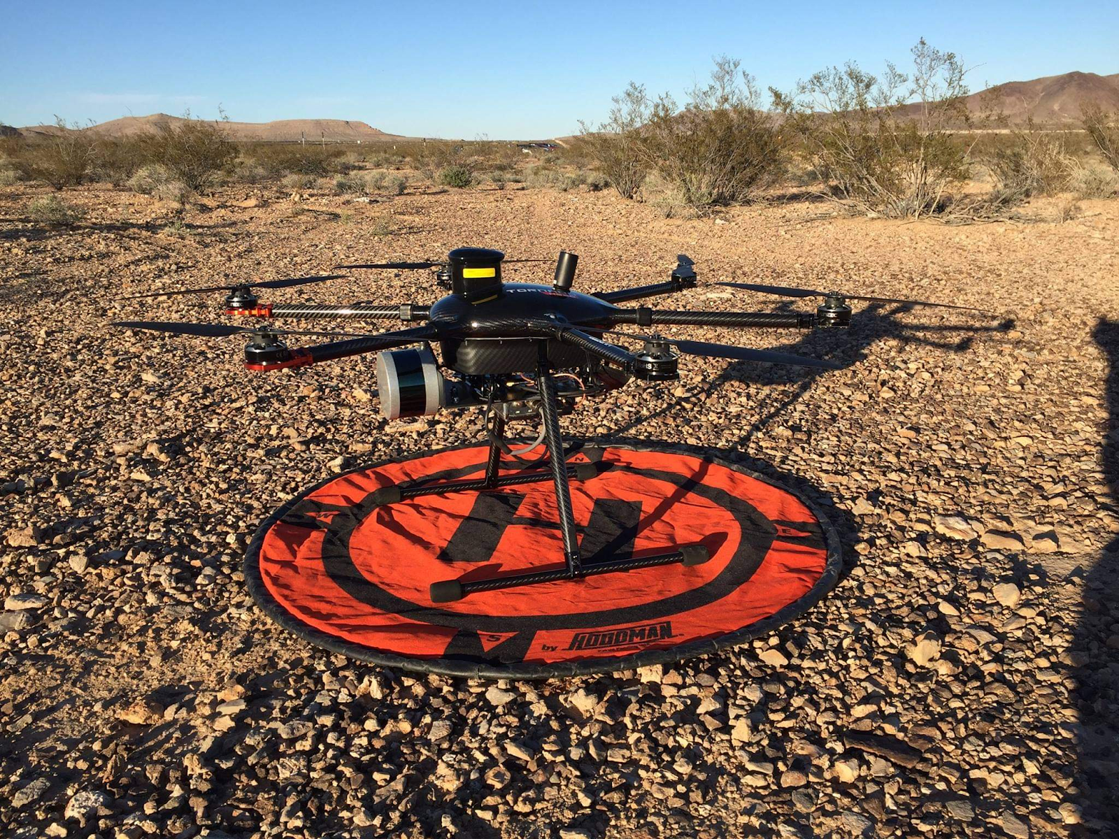
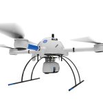
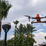
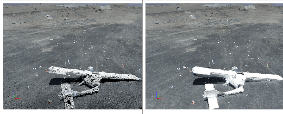
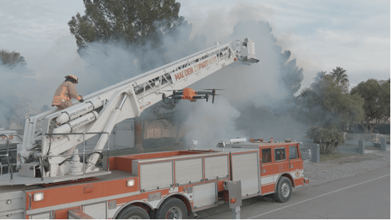
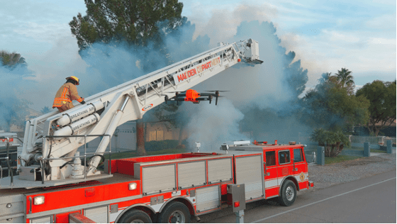
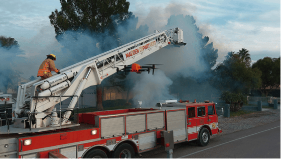
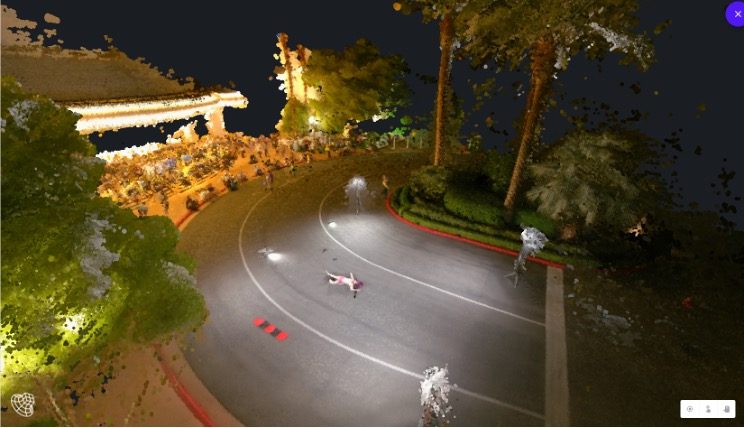
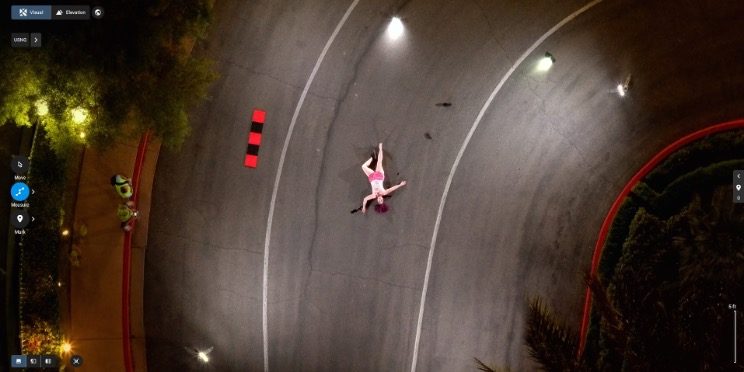
The above image is the author’s first experience with LiDAR; a Velodyne VLP16 with Geodetics IMU, mounted to a Yuneec H920 hexcopter.
With ever-increasing flight efficiency coupled with reduced weight and cost of LiDAR sensors, there are several aircraft and LiDAR systems available at affordable price points to suit virtually any budget. While LiDAR may not yet be for casual pilots, commercial pilots report near-immediate full ROI with LiDAR due to the current scarcity of complete systems.
Sensors may be purchased as a complete/total solution with aircraft, support software, and payload, or owners of medium lift systems may purchase LiDAR sensors separately to mount on whatever aircraft they’re familiar and comfortable with. For example, there are many LiDAR payloads available for the DJI Matrice 300 platform, Inspired Flight, Freefly, Yuneec, Maptek, Microdrones, and other systems.
LiDAR packages may be stand-alone, combined with separate RGB cameras for photogrammetry, or assembled with both in one housing. For example, the highly popular GeoCue 515 package not only offers a Hesai XT32 LiDAR sensor, it also includes two 20MP RGB cameras for colorizing the pointcloud, or for photogrammetry deliverables. Additionally, the system is designed for properly and precisely scaling RGB data on to the 3D pointcloud, providing not only a very accurate and precise model, but colorized, photo-realistic data for engineers, surveyors, construction teams, graphic designers, game designers, etc.
Pilots, engineers, program managers, surveyors will want to consider several factors when choosing a LiDAR payload for purchase or rent.
- Cost
- Penetration
- Resolution
- Software cost/flexibility
- Difficulty of operation
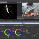
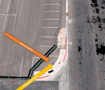
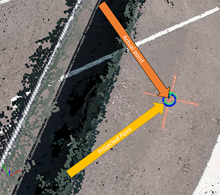
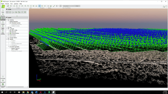
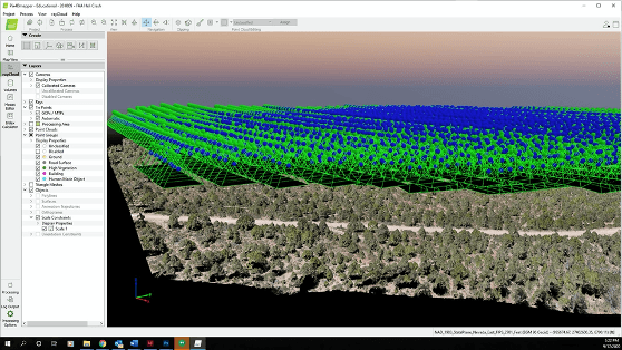
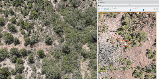
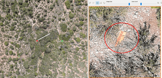
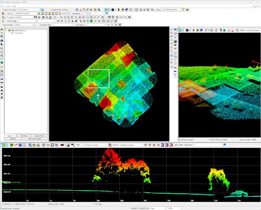
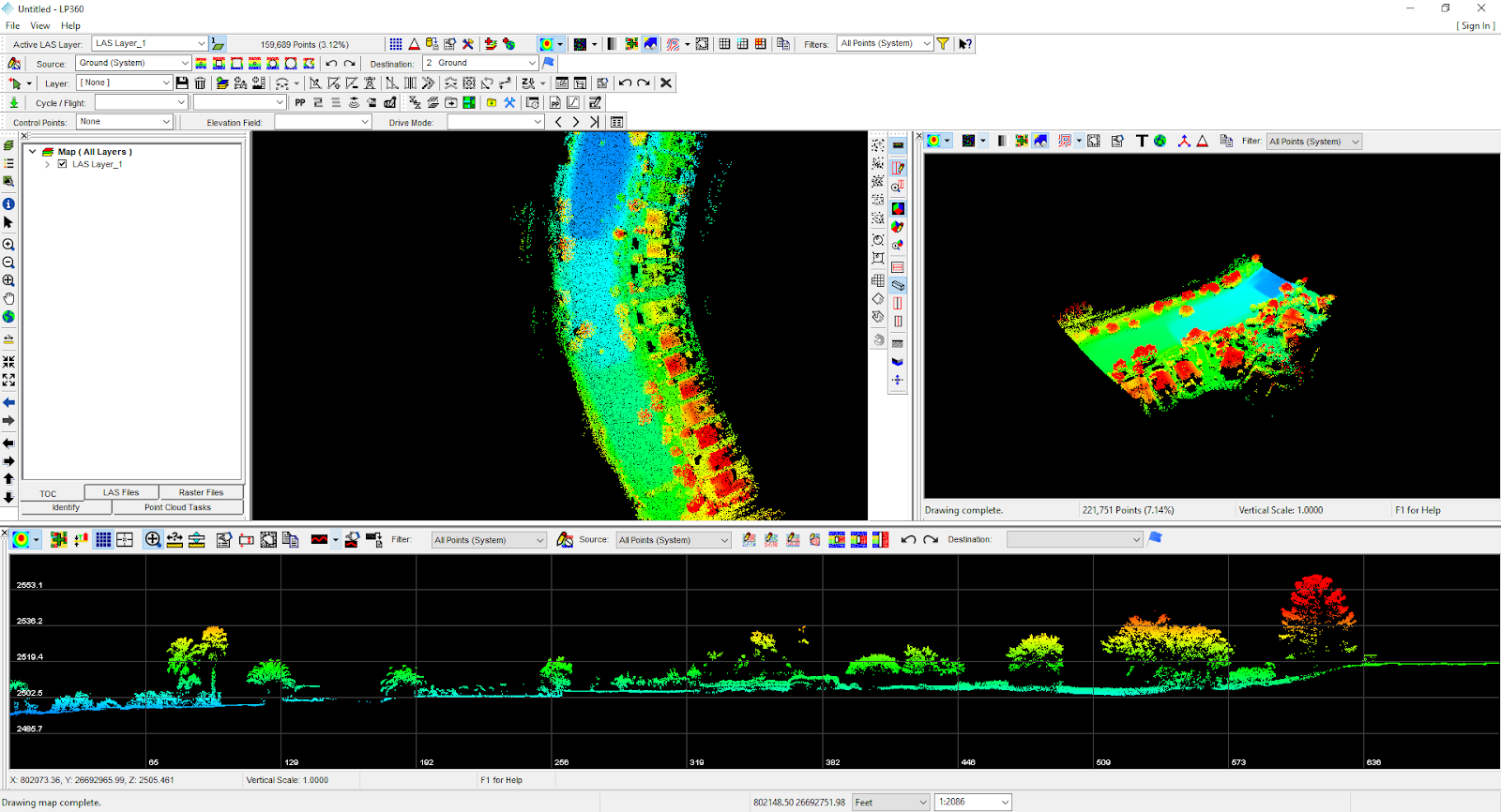
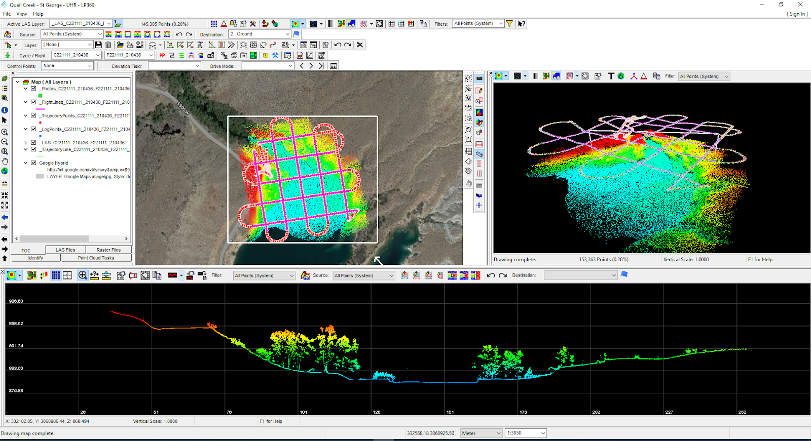
Different sensors will yield different results. Below are examples from the DJI L1, the Velodyne VLP16 (Microdrones HR), Hesai Pandar XT32 , and the Reigl Vux1 sensors. Profiles/cross sections captured from LP360 illustrate the surface data from the various sensors, and is a confident method of displaying vegetation penetration.
DJI L1
Microdrones MD1000HR (VLP16)
GeoCue 515
REIGL VUX1
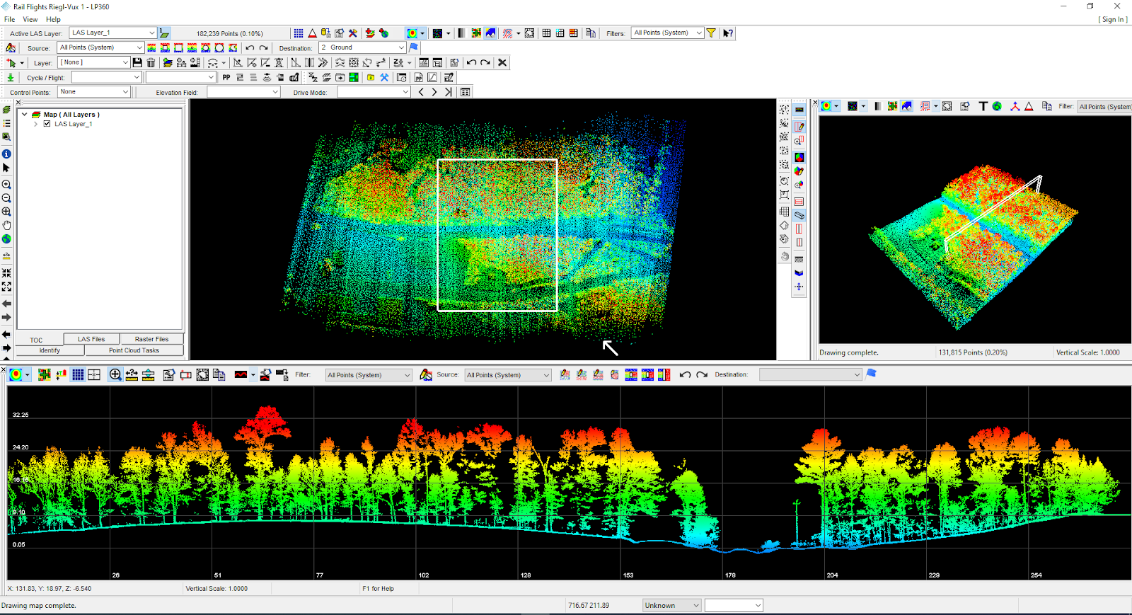
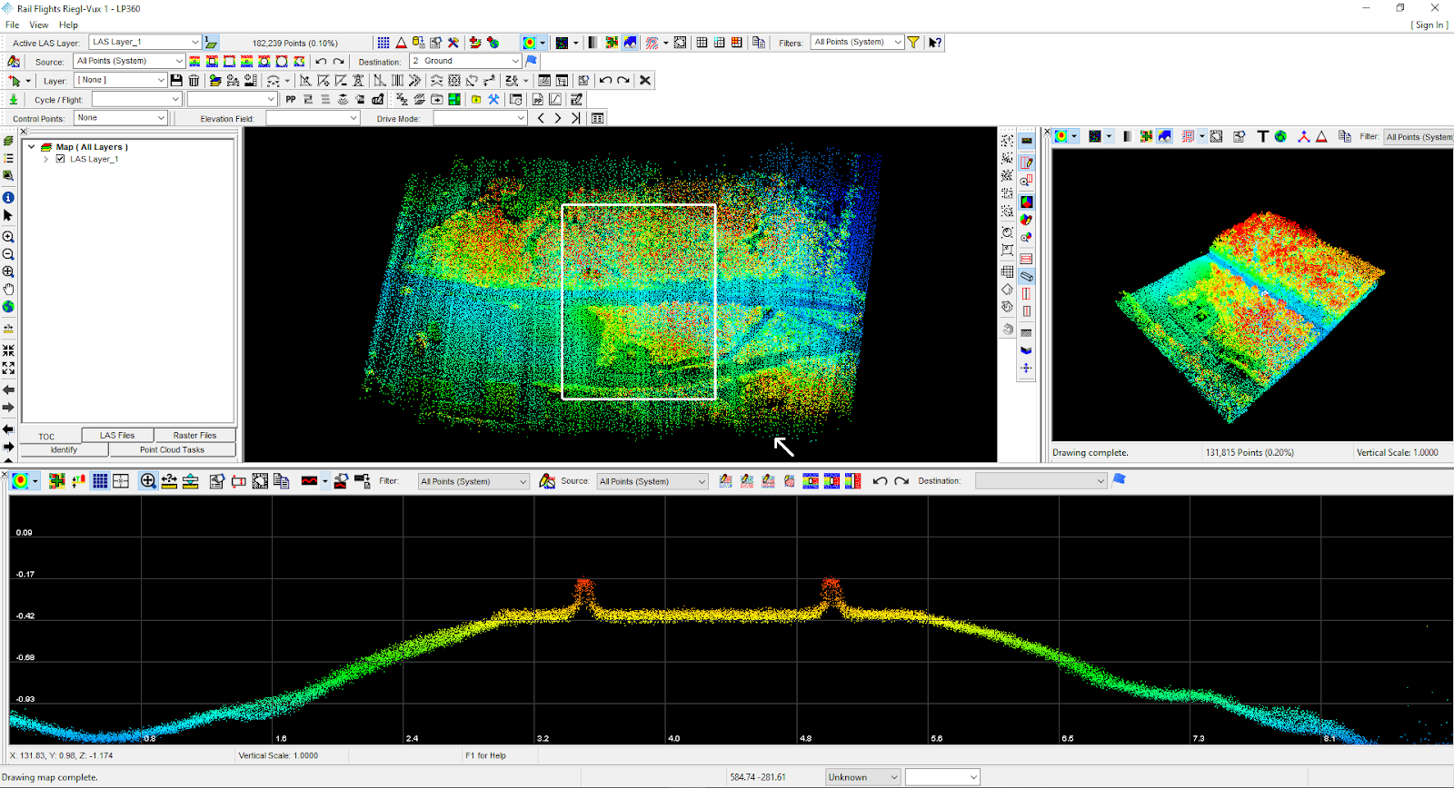
“Penetrating vegetation is a key function of LiDAR sensors; this is why tree profiles/slices have been used to illustrate these challenging scenarios.”
WHAT ABOUT SOLID STATE LiDAR SYSTEMS?
It is worth noting that solid state LiDAR systems are on the rise, and very much in development for longer-range with high density. Technology hasn’t improved to a point where solid state LiDAR might be broadly applicable for UAS work, while the technology has proved promising due to lighter weight, less power consumption, and speed. However, development is heavily focused on autonomous vehicles at present, yet it is fully anticipated we’ll soon see solid state LiDAR available for aerial applications.
HOW IS LiDAR DIFFERENT FROM PHOTOGRAMMETRY?
Photogrammetry uses multiple images with embedded geodata, matching pixels, and data information to create an orthomosiac. Pointclouds can be derived from images with slightly less accuracy, but a significant time commitment. A 50 acre field processed as a pointcloud derived from photos may take up to 12 hours on an average computer, while the same computer will process the LiDAR-sourced pointcloud in under 30 minutes. LiDAR is significantly faster to fly than UAS designed for photogrammetry, as the need for deep overlap is lessened in LiDAR workflow.
Additionally, LiDAR may be flown at night (unless colorization is needed) while photogrammetry requires daylight hours.
On the other hand, photogrammetry missions may be flown while there is water on the ground after a flood or heavy precipitation. LiDAR works best in dry, non-reflective environments. Mirrored windows, water reflecting on leaves, ponds, creeks, etc will display as blacked-out areas in a LiDAR scan.
Not all software applications are compatible with all the different LiDAR sensors. The way trajectories are read/displayed, how data is managed/handled, even basic features are very different between the various software tools available today. For example, until recently, the data from DJI’s L1 LiDAR system could only be initially processed in DJI Terra software, which is quite limited, and many feel is “kludgy and slow.” It’s also not a platform known for being stable.
Recently, GeoCue has added the DJI L1 to it’s compatibility platform, enabling DJI users to use the LP360 software with L1 data, with great stability, flexibility, and speed.
SOFTWARE
When choosing a LiDAR system, there are many considerations, the greatest of which is how important high resolution and precision at ground will be to projects/workflows. Budget frequently makes this determination. However, bottom line vs long-term needs are often at odds with each other; it’s wise to spend “up” to a higher grade LiDAR sensor when customer satisfaction is at the top of the list. Research often requires higher grade sensors as well.
When choosing a LiDAR system, consider the aircraft carrying the payload, the software required to process the data, and consider flight times as well. Two hours flying a narrow beam sensor vs 30 minutes of a wider throw may make all the difference, particularly when the company has a deep backlog and is focused on efficiency.
Whether LiDAR an organization is ready for LiDAR now, or down the road, there has never been a better time to learn more about LiDAR, pointclouds, and the differences of data processing from photogrammetry workflows.
Special thanks to Brady Reisch of KukerRanken for the profile slices of data.