

The Year of LiDAR
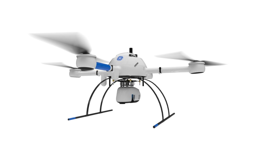
2022 is clearly the year of LiDAR. At all of the UAS shows in the USA, Mexico, Canada, and EU, the hot topic is LiDAR in 2022, and 2023 is ramping up to be more of the same, with significant growth. LiDAR is a “LIght Detection And Ranging” sensor, utilizing a laser, position-controlled mirror, an […]
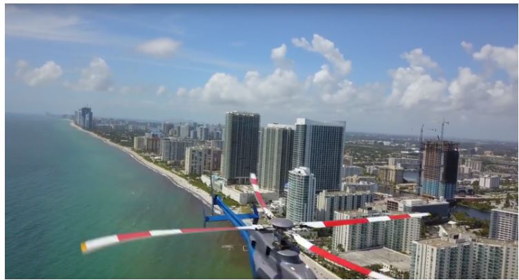
A Deep Insider’s Look at a Rugged Terrain Mission to Investigate a Helicopter Crash with Drones
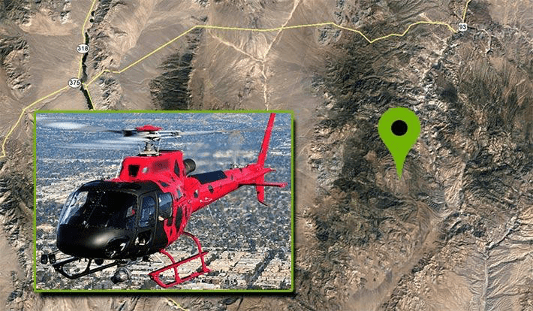
nce that may have not been seen for various reasons during a site walk-through.
Part 91, 101, 103, 105, 107, 137: WHAT’S THE DIFFERENCE?
All these FARs, what’s a drone pilot to do in order to understand them? Do they matter? YES! In virtually every aviation pursuit except for sUAS, an understanding of regulations is requisite and part of most testing mechanisms. As a result, many sUAS pilots holding a Remote Pilot Certificate under Part §107 are woefully uninformed, […]
Six ways drones have proven themselves as a tool for the AEC, Surveying, and mapping industries.
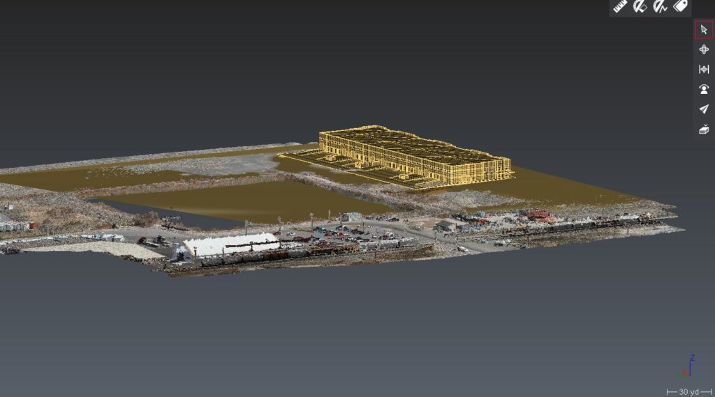
Drones and unmanned aircraft in AEC scanning and construction Six ways drones have proven themselves as a tool for the AEC, Surveying, and mapping industries Drones and unmanned aircraft in AEC scanning and construction process are becoming more common. Unmanned aircraft, or drones are becoming much more common on today’s project sites. many companies in […]